
 Photo transfer via cassette tape
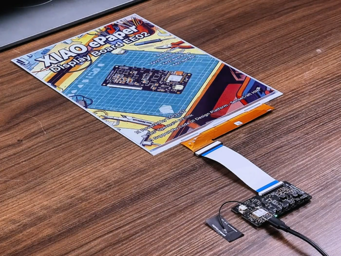
Lots of fiddling, lots of trial, lots of error. That is what describes the past weeks best. But most important, I’ve managed to get a photo transferred to the ePaper screen!
The concept in more detail
To test the concept of transferring data via audio, I’ve done many searches on Google over the past year and gathered some ideas. But they felt like a fragile chain of different technologies. So, I asked Google AI to help me with the research and provide clear examples.
Google AI concluded that transferring data via audio signals on a cassette tape is highly feasible. Because of the characteristics of the tape, it recommended using 16 pitches and a 20 ms duration for each pulse. With 16 pitches, you can transfer 4 bits (half a byte) per pulse on a single track. By starting with a Left-Right solution across 2 tracks, we can transfer 1 byte per 20 ms.
My ePaper screen has a resolution of 1200×1600 pixels. An uncompressed RGB888 image (24-bit) for this screen would be roughly 5760 KB (5.7 MB). At a 20 ms rate, this would take 32.77 hours to transmit.
Because of the nature of the Spectra 6 ePaper screen, which uses 6 pigment colors (black, white, red, yellow, blue, and green), we can apply the Floyd-Steinberg dithering algorithm first to match its color palette. Since there are only 6 colors, we can downsample the image to 4 bits per pixel. This means two pixels fit into a single byte, reducing the file size by 83% to just 960 KB. This brings the transmission time down to 5.33 hours at a 20 ms rate.
We can save even more on image size by pre-scaling the photo to exactly half its resolution (600×800 pixels). While decoding on the receiver, each pixel will be upscaled as a 2×2 block. This might sound like a loss of quality, but because the pigments on the ePaper screen must move physically, larger pixel blocks result in much stronger contrast and brighter colors. This scaling saves another 75% of the file size, bringing it down to 240 KB. At this size, the transmission would take 1.37 hours at a 20 ms rate.
Later, we can experiment with shorter pulse times (Google AI suggested we could try 5 ms) and use multiple tracks of an auto-reverse tape recorder. If that works, it should allow for a 10-minute recording and a 10-minute playback.
How does the principle work?
- Sender (ESP32 + Camera): The ESP32 takes a picture and converts the binary data into audio pitches using Multi-Frequency Shift Keying (MFSK). See the table below for the frequencies used for each tone and its corresponding 4-bit value. This audio is sent to the line input of a cassette recorder, which records it onto the tape.
- Receiver (ESP32): The cassette recorder plays the tape. The audio output (headphone jack) goes to the second ESP32. This ESP32 analyzes the pitches via an analog-to-digital converter (ADC) and a Fast Fourier Transform (FFT) to reconstruct the buffer of 4-bit pixels.
- ePaper (ESP32 + Screen): The ePaper driver board uses an ESP32 S3, but all pins are occupied and none are broken out. To solve this, we set up a WiFi Access Point on the ePaper board. The Receiver connects to this network and transfers the decoded pixel buffer to the screen.
To focus on the audio transmission first, I am taking a few shortcuts at this stage:
- No cassette deck in between yet; both the Sender and Receiver ESP32s are connected directly.
- To get the project started, I’ll limit the image size even further to 60×80 pixels.
Building on a breadboard
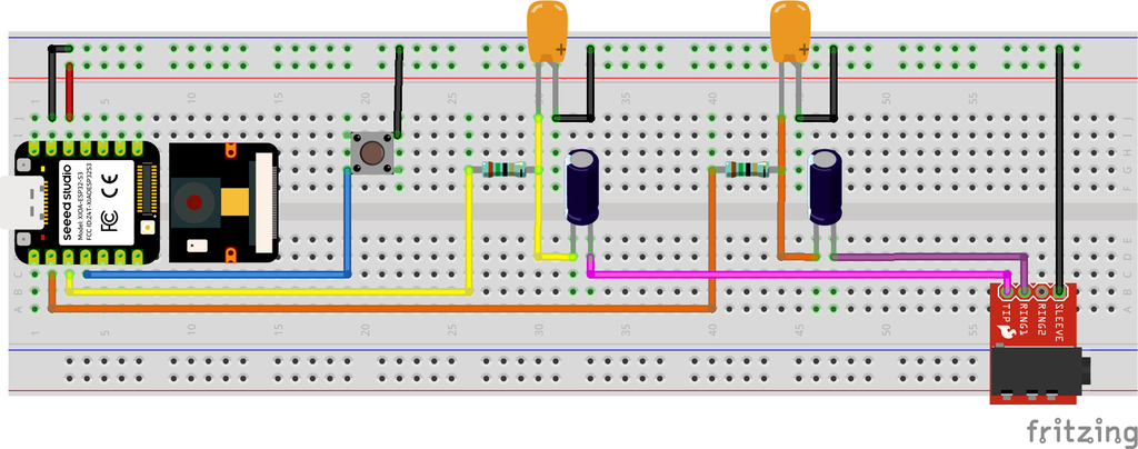
Google AI provided a pinout for the Sender, where the audio signal is generated using PWM. Since pure PWM produces square waves instead of the smooth sine waves needed for clean audio, low-pass filtering capacitors handle the smoothing.
As for the Receiver: a standard audio signal centers around 0 volts and has both positive and negative amplitudes. An ESP32 ADC cannot read negative voltages without damaging the chip; it requires a strictly positive voltage. By using a DC-bias voltage divider circuit, we lift the center voltage of the audio signal to a safe 1.83 volts.
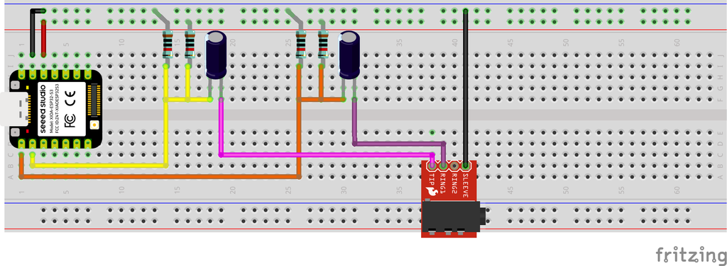
By building this on a breadboard with capacitors and resistors, there is a bit of tone-difference at the Sender and Receiver. The values are just a bit more then double and are mapped is as listed here. When using a real cassette tape later on, I do expect this needs new tuning.
| 4-Bit Value (Hex) | Sender Frequency (Hz) | Receiver Frequency (Hz) |
|---|---|---|
| 0x0 | 1000 | 2052 |
| 0x1 | 1200 | 2450 |
| 0x2 | 1400 | 2860 |
| 0x3 | 1600 | 3280 |
| 0x4 | 1800 | 3684 |
| 0x5 | 2000 | 4090 |
| 0x6 | 2200 | 4500 |
| 0x7 | 2400 | 4915 |
| 0x8 | 2600 | 5325 |
| 0x9 | 2800 | 5725 |
| 0xA | 3000 | 6140 |
| 0xB | 3200 | 6555 |
| 0xC | 3400 | 6958 |
| 0xD | 3600 | 7370 |
| 0xE | 3800 | 7778 |
| 0xF | 4000 | 8182 |
Code from AI
The AI-generated code for the Sender worked surprisingly fast and well. By adding a small speaker to the Sender, you can clearly hear the generated tones. It works!
The receiving side, however, was less of a success… The AI code for the Receiver required many tweaks over several weeks. After stepping in with a manual timing design (no AI, but my personal work), it finally worked. I had to slow down the transfer rate to 64 ms per pulse. That is three times slower than what Google AI initially promised…
Why the 64ms rate?
When receiving audio, the FFT collects 256 samples on both channels and analyzes the received tone. This process takes about 27 ms in total. When a tone change is detected, it could just be a transitional glitch, so we skip the first measurement. The second measurement captures the stable tone. Then we wait for the remainder of the 64 ms window. If the tone doesn’t change after this window, it signifies a repeated tone, indicating a consecutive pair of pixels with the same colors.
With this setup, I can now transfer a 400×300 pixel image (which shows as a 800×400 image) in roughly half an hour:
(Width × Height / 2 pixels per byte × 2 as we send half a byte per tone / 2 tracks × 64 ms rate / 1000 ms per second / 60 seconds / 60 minutes)
(400 × 300 / 2 × 2 / 2 × 0.064 / 60 / 60) = 64 minutes
A full screen image will take 4 times as long, 256 minutes or 4 hours and 16 minutes.
There is still plenty of room for optimization, but here is the code for the camera/sender, the receiver and the ePaper.
ToDo in the next version
I know there is (at least) one bug in the current code: the image being sent is not the image that was captured. This is likely a buffer reset issue that I will tackle in the next iteration.
Additionally, the WiFi connection between the Receiver and the ePaper is unreliable. After waiting so long for the audio transfer to complete, failing at the final upload stage is incredibly frustrating. In the next version, I plan to drop WiFi and use a wired serial connection, likely integrated into a custom PCB.
Finally, I want to process the audio across 4 channels. Technically, this would bottleneck a single FFT loop. However, the AI recommended utilizing both cores of the ESP32 S3: dedicating one core strictly to audio capture and the other to FFT processing. Switching the sampling method from the internal ADC to an external I2S module should also significantly speed up the capture rate.
